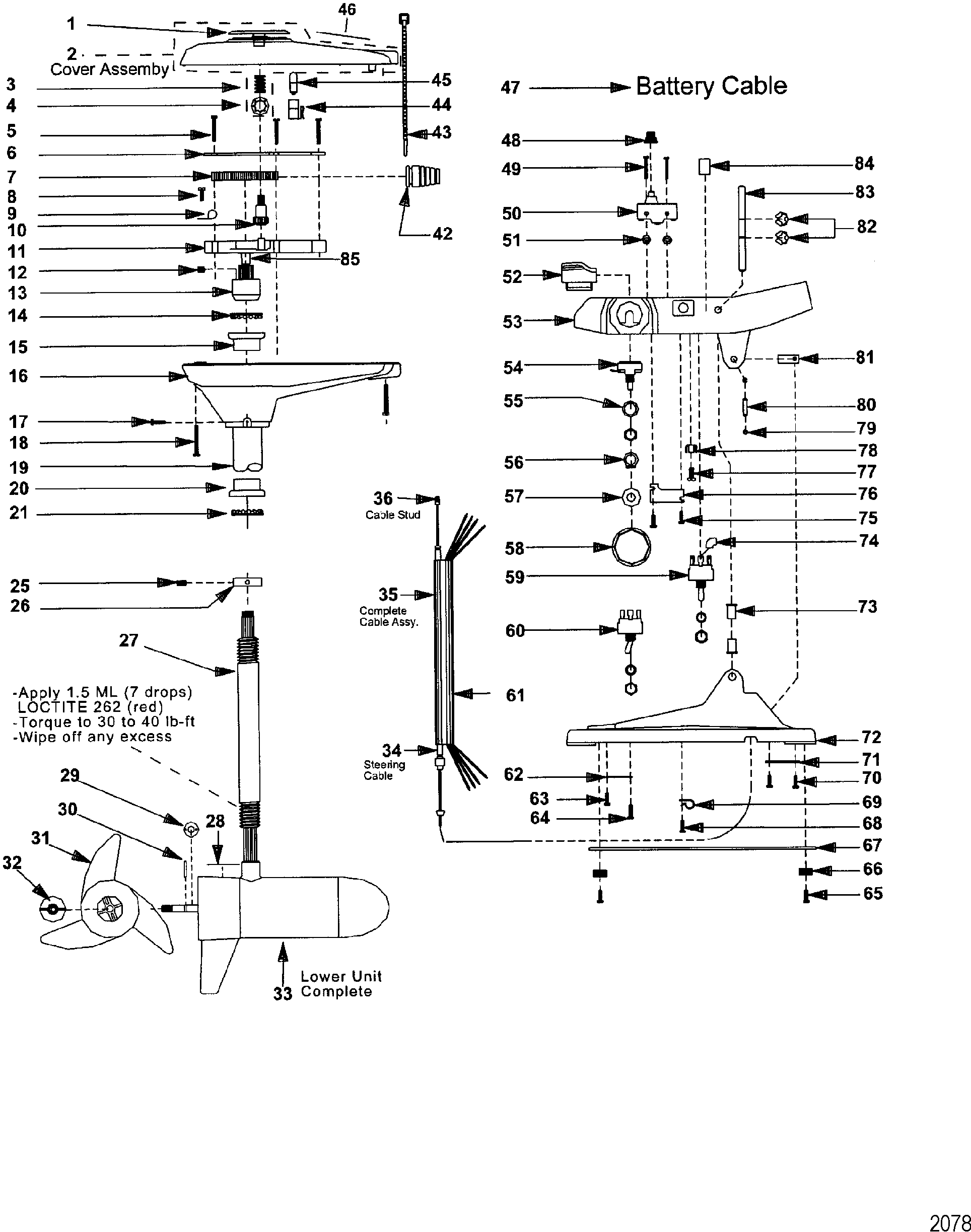
Trolling Motor Wiring Diagram

nest Hello Wiring Diagram, Nest Hello Advanced Wiring Diagram, 6.25 MB, 04:33, 63,749, gt8monster, 2018-06-16T10:14:46.000000Z, 19, Nest Hello Doorbell: 18 Questions/Answers You Need To Know - Smart Home Point, www.smarthomepoint.com, 1057 x 852, png, nest diagram hello doorbell wiring google camera chimes chime install multiple lh4 googleusercontent answers questions know need pre, 20, %ef%bb%bfnest-hello-wiring-diagram, Anime Arts
Installation diagrams 48 volt system the following schematic outlines the necessary accessories/cables needed to connect a trolling motor 1 to a 48 volt system. Trolling motor wiring diagram. Trolling motor wiring diagram from www. boatdesign. net. To properly read a electrical wiring diagram, one offers to learn how the particular components in the system operate.
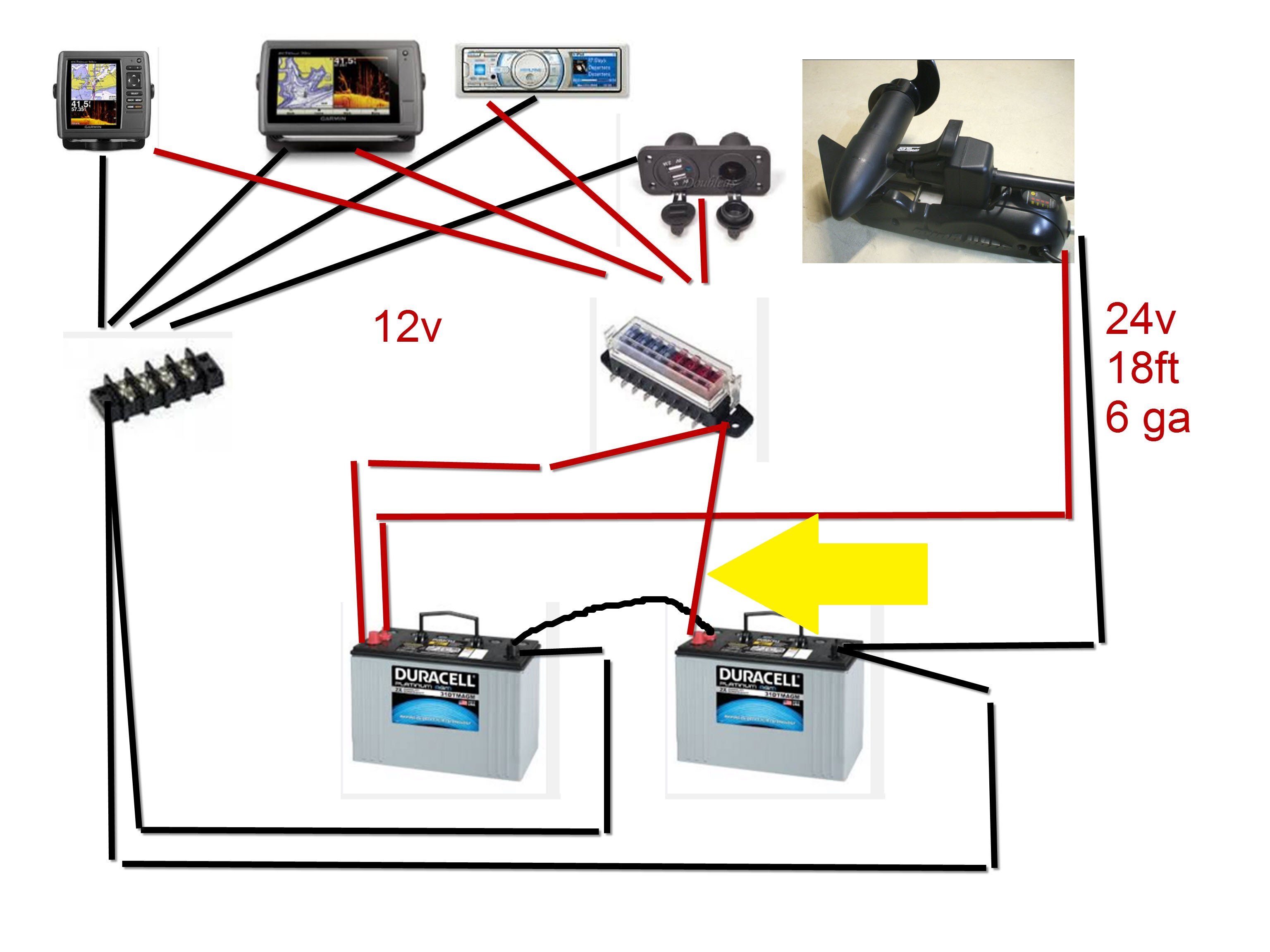
Now you have to connect the motor's negative cable with the negative terminal of the 2nd battery. Improper wiring of 24v could cause problems so be careful during the whole process. Use a circuit breaker here to protect yourself and your gear. So if you need more battery here, you will use a 36v trolling motor that will produce 112. Installation diagrams 48 volt system the following schematic outlines the necessary accessories/cables needed to connect a trolling motor 1 to a 48 volt system. We get many requests for schematics on trolling motor wiring. There are a few different configurations one can use according to your trolling motor application and existing wiring that the manufacturer installed in your boat. The images below should help you resolve just how trolling motor wiring should be connected. Installation diagrams 48 volt system the following schematic outlines the necessary accessories/cables needed to connect a trolling motor 1 to a 48 volt system.
12 24 Volt Trolling Motor Wiring Diagram | Free Wiring Diagram

Motorguide 24 Volt Trolling Motor Wiring Diagram - OURFMAILYCORNER
12 24 Volt Trolling Motor Wiring Diagram | Free Wiring Diagram

12 24 Volt Trolling Motor Wiring Diagram | Cadician's Blog
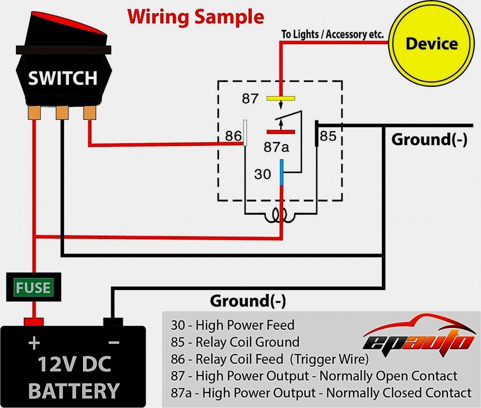
Motorguide 12 24 Volt Trolling Motor Wiring Diagram

Wiring Diagram Motorguide Trolling Motor
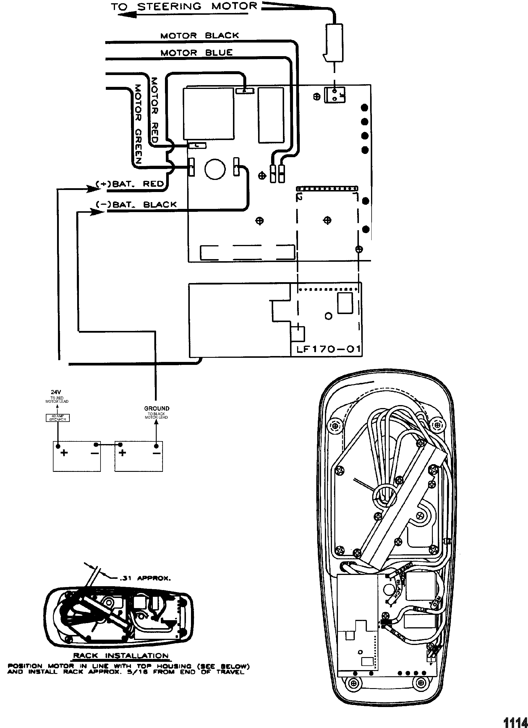
Minn Kota Trolling Motor Wiring Diagram | Wiring Diagram
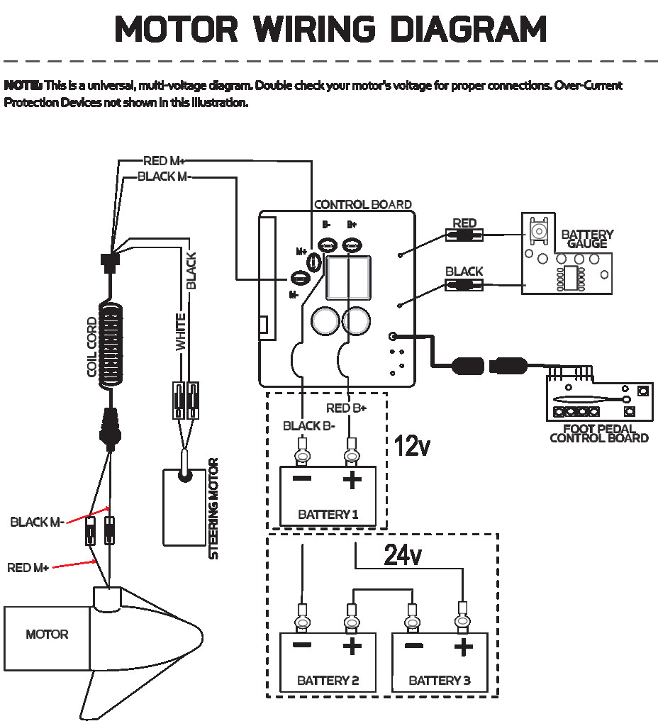
Wiring Diagram Motorguide Trolling Motor
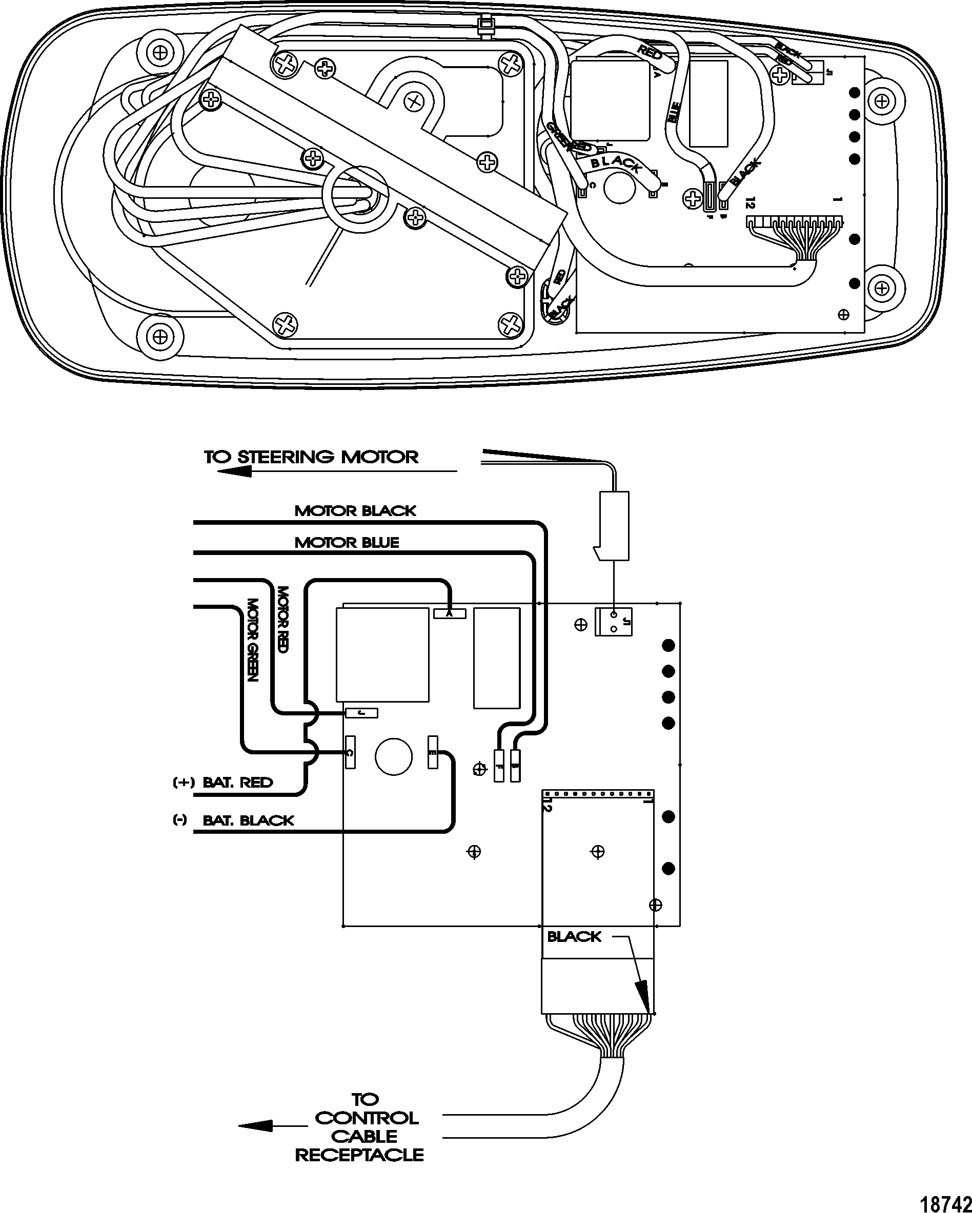
Evinrude Trolling Motor Wiring Diagram

Motorguide 24 Volt Trolling Motor Wiring Diagram
